-
How to drill holes in the photovoltaic panel base piles
A rotating auger drills into the ground, removing soil and creating a cylindrical hole. A down-the-hole hammer is attached to the drill string and strikes the bottom of the. . This guide is tailored for pile driving contractors and engineers involved in solar farm projects—providing an in-depth exploration of the techniques, materials, and challenges associated with pile driving in this growing sector. As the demand for renewable energy increases—solar farms are becoming. . That's exactly what happens when photovoltaic panel columns aren't buried deep enough. The industry standard for solar panel post depth typically ranges from 4-8 feet, but here's the kicker: 42% of solar installation failures stem from improper foundation work according to a 2023 NREL study. Let's. . den can be drilled effectively with augers. The selected solar panel is known as Top-of-Pole Mount(TPM),where it is deigned to install quickly and. . How deep should the holes in the photovoltaic bracket be drilled How deep should the holes in the photovoltaic bracket be drilled How deep is a drilled shaft pile for a solar array? Drilled shaft piles for solar array footings can vary anywhere from 6 to 24 inches in diameter and 5 to 30. . Solar plant construction involves a variety of specialized equipment and techniques to install the solar panels securely. A heavy weight (hammer) is raised. .
[PDF Version]
-
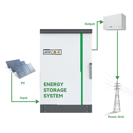
Zero-fire line diagram of photovoltaic panels
Follow these detailed steps to draw a comprehensive single-line diagram for a solar installation system that includes a PV array, a battery backup, and a standby generator:. Follow these detailed steps to draw a comprehensive single-line diagram for a solar installation system that includes a PV array, a battery backup, and a standby generator:. Solar, or photovoltaic (PV) panels as they're referred to in NFPA 1, Fire Code, are becoming more and more common on one- and two-family dwelling and townhouse roofs. Since the 2016 edition of NFPA 1, access pathways have been required on roofs to facilitate fire service access as well as egress. . Creating a compliant pv system single-line diagram (SLD) is a critical skill for any electrician working in solar. Ground-faults in PV arrays could potentially result in large fault current which may increase the risk of fire hazards. Space requirements and layout for photovoltaic and solar water heating system components should be taken into account early in the design. . The easiest way to draw electrical diagrams for photovoltaic installations is by using the EasySolar app, where such diagrams, including all necessary components, can be automatically generated. This schematic illustrates the power source, power distribution, electrical equipment, and how different parts of the system are connected. The importance of a comprehensive single line drawing for PV. .
[PDF Version]
-
Detailed diagram of DC line connection of photovoltaic panels
In this guide, we'll walk through how to design your wiring layout, the essential components you'll need, and how to interpret or create diagrams for both grid-tied and off-grid systems. . The single most important tool in your arsenal is a solar panel wiring diagram. This is your non-negotiable blueprint, a detailed map that ensures every component works together safely and efficiently. This definitive guide will cover everything from the core wiring methods to critical safety. . Solar panel diagrams are graphic representations of the connections you should make between each PV module and other components of the solar power system, including: Why Are They Important? Remember the saying, “Measure twice and cut once?” Detailed specifications with diagrams for reference help. . A solar wiring diagram is a detailed blueprint showing how all the components of a solar power system are interconnected.
[PDF Version]
-
Schematic diagram of automatic rotating photovoltaic panels
The Sun tracking solar panel consists of two LDRs, solar panel and a servo motor and NodeMCU. Two light dependent resistors are arranged on the edges of the solar panel. Light dependent resistors pro.
[PDF Version]
-
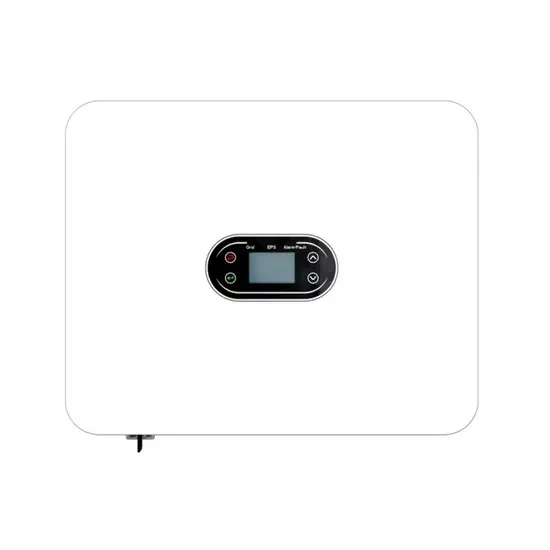
Inverter connected to photovoltaic panels diagram
A solar panel and inverter wiring diagram illustrates the connections and components needed to create a functional solar power system. The wiring process begins with the connection of the solar panels. . Solar panels are photovoltaic devices that generate electricity when exposed to sunlight, while inverters convert the direct current (DC) produced by the solar panels into alternating current (AC) that can be fed into the electrical grid or used to power appliances and devices directly. This component converts DC energy generated by solar panels into AC ener y at. . If you're installing your own solar power system in the comfort of your home, you've probably been faced with a decision about what necessary components to purchase and how to connect them. Proper wiring is crucial, both for proper function and for safe, reliable operation over the long term.
[PDF Version]
-
How to read the photovoltaic panel connection diagram
Reading a solar panel wiring diagram involves understanding symbols, circuit types (series/parallel), and safety protocols. . Read on to find out more about solar panel connection diagrams and how to wire PV modules to achieve the best performance based on your unique installation requirements. Most modern photovoltaic systems for residential or portable use don't actually require much “wiring. The diagrams of PV panels provide detailed information about the components within the system, their location, and how they are wired together. Knowing. . These are precise, computer-aided design drawings (think AutoCAD or similar) that lay out everything for your PV system: panel placement, wiring routes, structural attachments, grounding/earthing, electrical flow, etc. Key elements include PV modules, inverters, charge controllers, and grounding points.
[PDF Version]