-
Centralized control of independent microgrids
In centralized approach, the microgrid central controller (MGCC) is mainly responsible for the maximization of the microgrid value and optinization of its operation, and the MGCC determines the amount of power that the microgrid should import or export from the upstream. . In centralized approach, the microgrid central controller (MGCC) is mainly responsible for the maximization of the microgrid value and optinization of its operation, and the MGCC determines the amount of power that the microgrid should import or export from the upstream. . However, the control of microgrids is one of the important issues to focus on in order to overcome the challenges raised by high penetration of of renewable energy sources (RES). Depending on the responsibilities assumed by the different control levels, the microgrid can be controlled in. . SEL is the global leader in microgrid control systems, verified by rigorous independent evaluations and proven by 15+ years of performance in the field. These levels are specifically designed to perform functions based on the MG's mode of operation, such as. . The U. Department of Energy defines a microgrid [1] as “a group of interconnected loads and distributed energy resources (DER) within clearly defined electrical boundaries that act as a single controllable entity with respect to the grid.
[PDF Version]
-
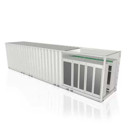
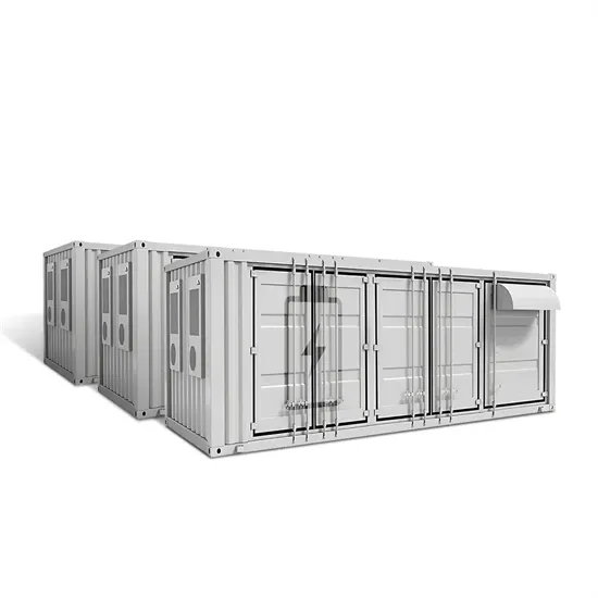
Basic knowledge of temperature control for container energy storage
Summary: Temperature control units are critical for optimizing energy storage system efficiency and lifespan. This article explores innovative thermal management strategies, industry challenges, and real-world applications for lithium-ion battery containers. Furthermore, a rule-based air conditioner control algorithm was prop s based on the external ambient temperature. Whether you are considering lithium-ion batteries, flow batteries, or any other type of energy storage technology, selecting the right temperature control solution is. . Containerized energy storage systems currently mainly include several cooling methods such as natural cooling, forced air cooling, liquid cooling and phase change cooling.
[PDF Version]
-
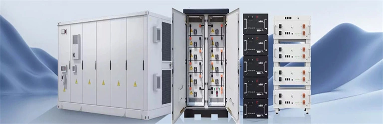
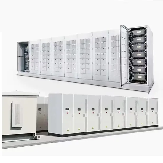
Energy storage linkage control system includes
The primary components include Energy Management Systems (EMS), Battery Management Systems (BMS), inverters, and energy storage modules. The EMS manages the flow of electricity, ensuring optimal use of resources while adapting to real-time demand. . Energy storage valveshave the advantages of high modularity, good economic benefits, and high operational reliability. Batteries are prone to thermal runaway in the event of short. . The three-level linkage control strategy between the battery management system (BMS), energy storage converter (PCS), and energy management system (EMS) in the energy storage system is the key to ensuring efficient and safe operation of the system. An EMS needs to be able to accommodate a variety of use cases and regulatory environments. The standard applies to all energy storage tec nologies and includes chapters for speci Chapter 9 and specific are largely harmonized with those in the NFPA 855 2023 edition. This will change with the 2027 IFC, which will follow th. . Summary: Modern fire protection linkage systems paired with advanced power storage solutions are transforming safety protocols across industries. A classic example is the kinetic energy stored in. .
[PDF Version]
-
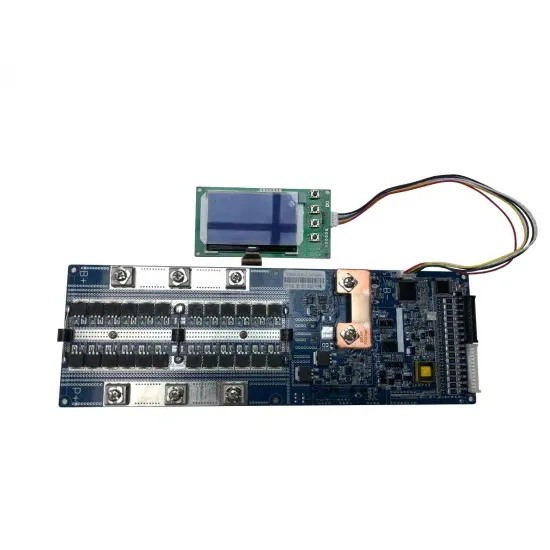
The composition of the Finnish BMS battery management control system
The below diagram shows these BMS building blocks. ) If the BMS is the brain of the battery, the controller is the brain of the BMS. This chip coordinates the functions of the BMS, monitoring the state of each cell. . A Battery Management System (BMS) is a crucial component in any rechargeable battery system. It's responsible for monitoring the condition of every cell in the battery pack and distributing the load accordingly, keeping track of important parameters including state-of-charge (SoC) and state-of-health (SoH). Their innovative platform is designed for effective fleet management and condition monitoring of industrial. .
[PDF Version]
-
Intelligent sliding mode fault-tolerant control of microgrid
Abstract: This work investigates sensor fault diagnostics and fault-tolerant control for a voltage source converter based microgrid (model) using a sliding-mode observer. . Describing the networked inverter in an AC microgrid as a multi-intelligent system and considering the voltage restoration problem as a tracking problem, a finite-time quadratic control strategy for microgrid voltages considering cyber-attacks is proposed. Some literature has proposed relevant solutions for actuator and sensor faults in microgrids., magnitude, phase, and harmonics) occurring simultaneously or. .
[PDF Version]
-
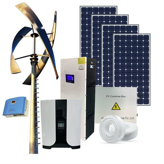
Solar control system installation
𝗛𝗼𝘄 𝘁𝗼 𝗶��𝘀𝘁𝗮𝗹𝗹 𝘀𝗼��𝗮𝗿 𝗽𝗮𝗻��𝗹𝘀 𝗮𝗻𝗱 𝘀𝗼𝗹𝗮𝗿 𝗰𝗵𝗮𝗿𝗴𝗲 𝗰𝗼𝗻𝘁𝗿𝗼𝗹𝗹𝗲𝗿 𝘄𝗶𝘁𝗵 𝗶𝗻𝘃𝗲𝗿𝘁𝗲𝗿 𝗮𝘁 𝗵𝗼𝗺𝗲. In this detailed tutorial, we'll walk you through each step of the process to ensure you harness solar energy efficiently and. . Timeline Reality: The complete solar installation process typically takes 60-120 days from consultation to activation, with permitting being the longest phase (30-45 days) rather than the actual installation (1-3 days). Through this discussion, we aim to. . As solar + storage installations continue to expand across residential and commercial projects, electrical safety, load management, and system coordination have become essential components of modern energy design. One of the biggest advancements addressing these needs is the introduction of Power. . Installing a solar kit at home is easier than you think with the right equipment and good guidance. The process involves more than just placing panels on a roof; it's a structured sequence of events requiring careful planning and execution.
[PDF Version]